It is now time to start building the framework for the GRV-2. For the most part I will be building the frame out of .060 wall square tubing. This is the same tubing I built the Turbotug out of and also the GR-7 engine frame. The truth of the matter is that this square tubing is cheap and easy to work with. Square tubing also has a higher torsional strength than round tubing which should help reduce frame twisting. With the aid of my trusty 64-1/4 band saw I chopped up a few pieces to build the rear wheel assembly. Using my TIG welder I tacked together several pieces which will eventually hold the axle bearing hangers.
The geometry of this build will be a little more complex than my GRV-1 project. Several parts of the bike will have awkward angles to deal with due to the use of square tubing. This is one of those instances in where the diagonal supports of the rear frame will intersect the flange at a 30* angle and require help to make the joint work. To fit the supports into place I needed to make a notch in the flange with my plasma cutter. This notch will allow the square tubing to extend all the way to the base of the flange for maximum support. Im sure you have noticed by now that this will be a hard tail design, meaning that it will have no active rear suspension. The main reasons for this is to simplify the design and reduce weight. The ground surface that the bike will be running on will be relatively smooth (IE dry lake bed). A rear swing arm and coil over shocks will just add weight and in my opinion not look the part of a true chopper.
Using my TIG welder to tack the frame pieces together is a new process for me. I discovered that I can tack the frame together with the TIG a lot easier than the MIG and do it without any metal splatter. This is priceless considering I can do this on my workbench without worrying about burning metal falling in my lap ;0)
Once the pieces were checked for squareness I proceeded to weld them with my trusty MIG welder. Note: It is important to know what order you are going to weld the joints if you are concerned about warping. Steel will shrink when it cools causing serious stresses in a metal frame. The key is to try to weld the joints in an order that locks the desired shape in first and then weld the joints that will threaten this shape. Sometime it is necessary to weld in temporary braces to help hold the shape of the frame while welding. Luckily for me my frame is fairly simple and will only require a little attention to the welding order.
I decided to add a set of lateral supports for the bearing hanger piers. These supports will keep the piers from moving if a lateral force should be applied to the rear wheel when riding.
The whole assembly was refitted to the engine in preparation for the bearing hanger plate installation.
By using a spirit level I was able to level the engine frame and then use that level as point of reference for installing my bearing hangers. You will notice the level placed on the two hangers below. This is done to assure that the bearing hangers will be welded on at the same height ensuring a level axle. This process works very well and I will be using it throughout the project to check the trueness of the frame as I build it.
Now that the hangers were in the right place I final welded them with the MIG.
I used my angle grinder and 80 grit flap disc to smooth out the exposed welds. I really like this finished appearance and it hides my marginal welding job ;0)
The rear axle I will be using is a 1 keyed aluminum go cart axle. I needed to shorten it up to be used with the golf cart wheel I am using. The axle was cut to length with my bandsaw with the aid of a little cutting oil.
I was now ready for installation of the wheel and layout of the brake caliper.
The rear wheel I am using for this project is a DOT rated 205/50-10 Carlisle Tour Max golf cart tire supported by a Douglas aluminum rim. This was part of a setup for a DIY mini-chopper that I won on eBay. The center hub and brake disc was also made for a mini-chopper which will work perfectly for my needs. The heavy bearings and stout axle will surely support the weight of the bike and its rider. I decided to go with the wide rear tire for a couple of reasons: A) if I ever convert this project to a turboshaft drive I will have enough traction to handle the torque and B) it just flat out looks cool!!!!
In order to add brakes to the rear wheel I needed to figure out how to bolt the brake caliper to the frame. I mounted the wheel to the frame and started to look at my options. So far so good ehh???
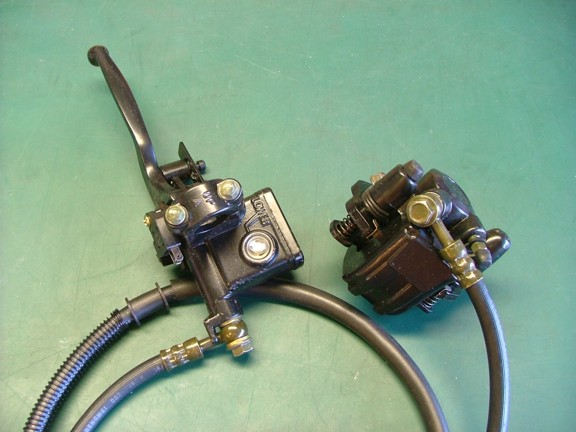
The braking system I will be using is from a Chinese ATV. The left side brake lever was made to control the rear brake of the ATV which is traditionally done with a left side foot pedal. I will use this handlebar lever in leu of a foot brake to simplify my frame design. I am not using a clutch lever for my engine so the left side lever is not in the way.
Since the stock rubber brake line supplied with the calipers is not long enough to make it to the rear wheel I will need to replace it. My plan is to use a 3/16 steel brake line from the back of the bike and up to the middle of the frame. I will then transition to a high pressure nylon tubing which will extend up to the master cylinder lever on the handlebars. This nylon tubing is the same stuff used on racing go carts for their brakes.
In order to make this new brake line system work I will need to convert the stock banjo fitting threads on the caliper to an 1/8 NPT thread to be used with standard tubing fittings. I disassembled the caliper to tap out the stock threads to the 1/8 NPT thread. Cutting oil always helps.
Once the caliper and master cylinder were tapped out I installed 1/8 pipe plugs to keep dirt out of the system.
The caliper was placed on the disc and measurements were taken to fabricate a caliper bracket. Notice that the caliper is on the top of the axle. This is to take advantage of the stock bleeder port on the top of the caliper. If the caliper is mounted to the bottom of the axle I would have no way to bleed the air out of the system upon filling of the brake fluid.
A caliper bracket was cut out of a heavy piece of angle iron. This bracket will weld directly to the left bearing hanger.
The caliper was installed to the bracket (not shown) and tack welded into place on the bearing hanger before disassembly of the rear wheel. The bracket was then welded onto the bearing hanger as seen below.
Since I had the rear assembly removed from the engine frame I decided to weld on the rear fender support. This support will hold the top end of the fender and also add a little strength to the frame.
The rear assembly was given the flap disc treatment and then remounted to the engine frame. You will notice that I added two more 3/8 holes for hardware to the bottom of the flange. This is to help distribute the wheel load more event to the engine frame. A total of six - 3/8 grade 8 bolts will be holding the rear assembly to the engine frame.
The caliper was now bolted to the frame and readied for the axle and disc.
Once together the disc and caliper mated beautifully. The wheel moves freely and without any intermittent rubbing. I would call that a success!!!
I now have the rear wheel assembly complete and it looks quite tough. It sort of reminds me of the Batman motorcycle Batpod in The Dark Knight movie :0) I can assure my readers, that is not what I am going for. However the Batpod is cool looking :oP
Well Im just about ready to tackle the front end of the Turbochopper. With any luck I should have the bike rolling very soon. Of course rolling is far from being able to ride but still, progress is progress!!!
Please join me again as I forge ahead on the next episode of the GRV-2 jet bike project!!!