|
|
 |
|
|
My hopes are to design a turbine system that is made from off the shelf materials. This project will not be easy but a good challenge is always fun. So far, there are really no exotic parts on the GR-1 and I hope to be able to prove that this can be done on a reasonable budget. The only hitch on my project is that more and more of my design is influenced by the use of the mill and lathe. These tools are proving to be essential to building anything rotary and I feel that I will use them a lot more than I anticipated before.
By putting the exhaust diverter (elbow piece) on a turntable, I was able to locate the center of the housing on the back side of the elbow. This location is where I cut out for the bearing tube heat shield using a hole saw. The hole saw must be parallel with the flange so as to allow for the angle of the heat shield to the elbow.
|
|
|
|
I took a piece of 2 EMT and welded a 1/4 steel plate on one end. I made the steel plate fit great by turning it on the lathe and I also bored a 11/16 hole in the middle of it for the drive shaft. After I ground off the rough weld, I chucked it up on the lathe and turned the face flat to mate with the turbine wheel. The heat shield is now ready for installation but there is one more thing to do before I weld it into place.
I wanted to make the internal flow of the gas with the least amount of back pressure as This will make the engine run cooler and not overheat the bearing. I made sheet metal shroud that diverts the flow of gas around the bearing tube heat shield. I tacked them into place and fit checked the tube in the hole. After some grinding and alignment, I welded the tube into place.
|
|
|
|
The alignment of the tube was difficult as I had to check it to be centered and perpendicular to the flange side so the turbine wheel will mate correctly. There are many variables working against the success of this project so I am sure that there will be some trial and error to experience. I ground the tube flush with the back of the elbow to finish the piece.
|
|
|
|
I am now ready to start building the stator section of the turbine. The stator will mount inside of the expansion duct and will be removable so that I can experiment with other designs. I started by making a cone shaped center for the stator section. For this I used 2 EMT and made a template for the cuts needed to bring the pipe to a point.
|
|
|
|
I temporarily mounted the nose-cone to the heat shield for a thermal test run on the engine. After bolting on the housing to the GR-1, I ran the engine for a few minutes to see if there was any warping of the housing. After getting stung by a angry wasp, I learned that the jet blast had evicted a nest of wasps under the eve of my house :0(
I disassembled the housing and started planning my stator section. One of the handy tools I bought was a rotary table. The table allows me to index parts to be machined by giving me a rotary plane that can be set to any of the 360 degree adjustments on the table. This means that I can build a jig to weld on my turbine blades at given places around the turbine wheel. This will allow me to get greater accuracy on the placement of turbine blades.
I cut down the nose-cone to the final length and drilled a hole on the tip. this will allow me to use the tail stock on the lathe for support when I turn the blades.
|
|
|
|
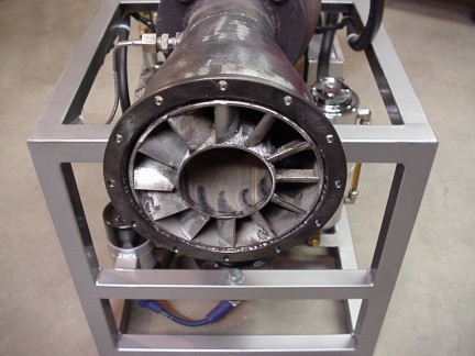
I then set up my rotary table on a jig I made for blade placement. This jig will allow me to weld on each blade at the same angle and attitude on the stator nose-cone/hub. To place the twelve blades on the stator I divided 360 degrees by 12 and every 30 degrees will be placed one blade. I needed to center the stator nose-cone/hub on the rotary table so the blades will be perfectly radial. I did this with a dial indicator and patience.
|
|