Well Im back at it this week and I hope to get a lot done on the 6CI project. I had just finished up the cylinder and now I need to machine the cylinder heads. This kit includes two castings for the cylinder heads that are close to the finished dimensions which should be quick work for me to complete.
The outboard head posed a little bit of a challenge for me as it does not have a surface to grab so it can be turned on the outside face. I decided to cheat a little by grabbing the raised ring on the outside face of the head with the three jaw chuck. Since the ring is too shallow to be used as a sole support for the head I needed to push on it with the tail stock to keep it in place.
I used a scrap piece of aluminum (seen below) to act as a go-between from the live center point to the flat inside of the head. The aluminum bushing kept the point of the live center from connecting with the disc and acted as a grip for the rough cast surface. It actually worked quite well :0) I cut the outer face of the head to the same dimension that I used for the crosshead frame flange (2.775 dia).
After the outside face was cut to size I was able to mount the head in the chuck and face the inside. I cut the head to .30 thick from the outside surface to the finished inside surface (the plans call for .25 FYI). You will notice the shoulder that was cut on the inside of the head, this is to keep the head centered in the bore of the cylinder. The shoulder also keeps the dead volume of the cylinder as low as possible which will help reduce steam usage when the engine is running.
I decided to not machine the outer face of the cylinder head so it can retain its cast iron look. Just a personal preference....
The next step was the inboard head. Unlike the outboard head this head has a gland seal boss that can be used to mount the casting to the lathes chuck.
I machined the outer face of the inboard head with a carbide tool bit.
I then finished the inside of the head where it meets the cylinder.
The cast iron alloy used in this kit is very easy to machine. I am not sure what type of alloy it is (maybe a gray type of cast iron). Either way I have a feeling it has a good nickel content as the machineability of the castings seem to be uniform throughout the thickness of the metal (not always the case with some castings). The color of the castings are also somewhat nickel in color on the surface.
I machined the gland seal boss on the frame side of the inboard head. You will notice that I used the 1/4 round tool bit for the neck of the boss. Not necessary but adds a finished touch to the part :0)
The next step was to bore the piston rod hole in the inboard head. I used a standard 5/16 drill bit to make the hole as seen below. Notice the tool bit used as a steady rest for the drill.
A 7/16 drill bit was used to drill out the top of the bore for the gland seal packing nut threads.
I used a bottoming style four flute 1/2-20 tap to thread the gland seal bore. I mounted the tap in the tail stock chuck to keep it axial during the cut.
I hand-fed the tap into the head by manually spinning the lathes chuck. This is because the lathe does not have a low enough gear to safely tap the head.
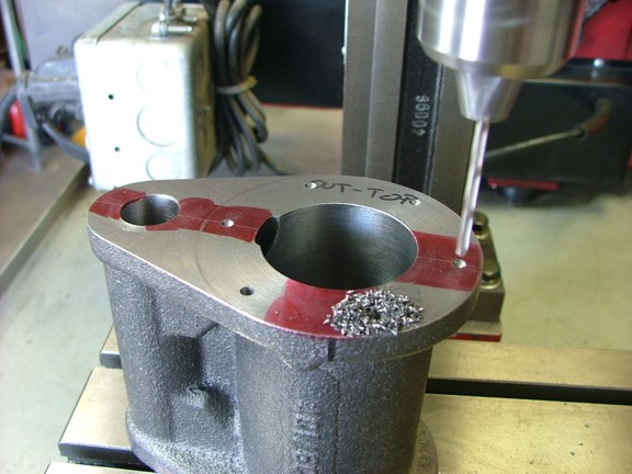
You may have noticed that up until this point that I have not drilled the cylinder of heads for the head bolt hardware. This is because I planned on using the heads themselves as drill jigs to properly align the holes with the cylinder. This way I will be guaranteed a perfect fit when I go to install the head bolts later on. I decided to drill the initial location holes in the heads with the aid of my rotary table. I centered the outboard head on the table with my dial indicator checking for any wobble when the table is turned. Once the head was centered I could move on to the layout phase.
To lay out the holes for the outboard cylinder head I used the degree wheel on the rotary table. Since the holes on this head are evenly spaced I can use a 60° separation between holes. All I have to do is find my radius and then dial in where the hole should be on the rotary tables degree indicator.
I used my center finder tool to dimple the hole centers on the head first. This way I can be sure the clamps will not interfere after the first few holes. I then used my center punch to define the dimples as hole centers.
I drilled the centers (with the aid of the rotary table) using a #25 drill bit (.1495). These holes will later be used to center the tap holes in the cylinder head (and crosshead frame). They will then be drilled out to 13/64 to make room for the 10-24 head bolts (plans call for 7/32 FYI).
And now for the inboard cylinder head. I centered the head on the table as before with the dial indicator.
You will notice the aluminum disc on the bottom of the head. This is a scrap piece used to prevent the drill bit from hitting the rotary table on accident.
Now this particular hole pattern is different from the outboard head. Four of the six holes are closer to each other due to the irregular casting pattern of the crosshead frames flange. The kit offsets the two top and two bottom inboard cylinder head bolts to miss the frames support webbing. Because of this I had to do a little math to figure out the degrees of separation between holes. Using a little of trigonometry I was able to figure out that the top and bottom holes were 25.628° off of centerline (centerline being a vertical line on the center of the bore of the cylinder). The other two horizontal holes had no offset and could be put at 0° and 180°. So..... I set up the inboard head to be drilled at the first horizontal hole, 0°. I then rotated the table to 64.372° for the second hole (25.628° from vertical). The third hole was at 115.628° (2 x 25.628°), fourth at 180° (the other horizontal hole), the fifth hole at 244.372° and the last hole was 295.628°. Once the hole pattern was dimpled with the center finder tip I was able to center punch them for drilling.
The #25 drill was used to drill out the holes as seen below.
I now had my two drill jig patterns to drill the cylinder and frame. All I had to do now was mark out the vertical and horizontal centerlines on the cylinder and frame to correctly align the drill jigs.
Using a c-clamp I was able to hold the head/drill jig to the cylinder for drilling. I used the #25 drill to dimple the cylinder so the holes could be finished after the head was removed.
The dimples were easily drilled out once the head was removed. Note: I had noticed that the hole above the steam port would be too shallow if drilled to miss the port. Because of this I decided to drill into the port expecting to use thread sealant on the 10-24 bolt that will later hold the head on (to prevent leakage). The outer head could be shifted to miss this port but the inboard heads horizontal bolt will still hit the inboard port. For me it is OK to use a little Teflon tape on the head bolt ;0)
And now for the inboard head.....
Using the inboard head I was able to dimple the crosshead frame just as I had done with the cylinder (matching the set). Note: I had made indexing marks on both the inboard and outboard head so the parts could be assembled with the same orientation later on.
I was now able to drill out the #25 holes in the heads with a 13/64 drill bit to allow for the 10-24 head bolts later on. Notice the index mark on the head below.
The #25 holes in the cylinder could now be tapped out with the 10-24 tap. I used the mill to hold the tap vertical while I hand-tapped the holes (manually turning the chuck to prevent tap breakage).
I also drilled out the frame with the 13/64 drill bit at this time.
At this point I decided to drill out the oiler hole in the top of the crosshead frame (not shown). I used a 5/32 drill bit to make a hole 2.31 back from the crankshaft side of the frame for the oiler. I then tapped the hole out with a 3/16 x 40 tap (for the future drip oiler). You can see the hole in the frame below.
Before I bolted everything together for a fit check I decided to add a set of drain ports to the cylinder. The kit gives you the option of adding these ports in a set of bosses under the cylinder as seen below. The drain ports will allow me to drain off steam condensation or excess cylinder oil from the engine without removing the heads. I will eventually install a set of globe valves into these drain ports.
You will notice that I did not drill all the way through with the 5/32 bit for the 3/16 x 40 tap. I used a 1/8 drill to meet the cylinder at the last 3/16 of the bore so the hole in the cylinder is not too big. I did not want the Teflon ring on the piston to have to ride over the edge of a big hole......
And now for the fit check!!!
The parts bolted together beautifully :0) I decided to order a set of longer 10-24 fillister style head bolts to custom fit them to the frame side of the cylinder (not shown). I cut the 2 bolts (actually screws, McMaster-Carr Cat #91794A253) to the right depth as to secure the cylinder correctly.
The engine is looking good so far and I cant wait to see it run for the first time! Join me again next time when I machine the valve heads in the continuation of the 6CI steam engine project!! Till then be safe my friends!!!